

Various Alternators in different
power plants with specification
An alternator is an electrical generator that
converts mechanical energy to electrical energy in the form of alternating current. For
reasons of cost and simplicity, most alternators use a rotating magnetic field with a stationary armature. Occasionally,
a linear alternator or
a rotating armature with a stationary magnetic field is used. In principle,
any AC electrical generator can
be called an alternator, but usually the term refers to small rotating machines
driven by automotive and other internal
combustion engines.

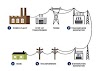
An alternator that uses a permanent magnet for its magnetic field is called a magneto. Alternators in power stations driven by steam turbines are called turbo-alternators. Large 50 or 60 Hz three-phase alternators in power plants generate most of the world's electric power,
which is distributed by electric power grids
Different
types of alternators include:
- Turbo generator – used in power
plant
- Automotive alternators – used in modern automobiles.
- Diesel-electric locomotive alternators – used in diesel electric
multiple units.
- Marine alternators –
used in marine applications.
- Radio alternators –
used for low band radio frequency transmission.
- Brushless alternators – used in electrical power generation
plants as the main source of power.
1.
Turbo generator
A Turbo generator set or turbine generator set is the
compound of a steam turbine or gas turbine shaft-connected to a fast running electric generator for
the generation of electric power.
Large steam-powered turbo generators
provide the majority of the world's electricity and are also used by
steam-powered turbo-electric ships.
Small turbo-generators with gas turbines are often used as auxiliary power units (APU,
mainly for aircraft). For base loads diesel generators or gas engines are usually preferred, since they offer
better fuel efficiency; however,
such stationary engines have
a lower power density and are built only up to about 10 MW power per unit.
The efficiency of larger gas turbines (50 MW or more) can be enhanced by using a combined cycle, where the remaining energy of hot exhaust gases is used to generate steam which drives another steam turbine on the same shaft or a separate generator set.
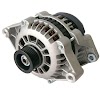
2. Automotive alternators:
An automotive alternator is a three phase generator with
in rectifier circuit consisting of six diodes. As the sheave (most people call
it a “pulley”) is rotated by a
Belt connected to the automobile engine’s crankshaft, a
magnet is spun past a stationary set of three-phase windings (called the stator),
usually connected in a Y configuration. The spinning is actually an
electromagnet, not a permanent magnet. Alternators are designed this way so
that that magnetic field strength can be controlled, in order that output
voltage may be controlled independently of rotor speed.
This rotor magnet coil (called the file coil, or simple
field) is energized by battery power so that it takes a small amount of
electrical power input to the alternator to get it to generate a lot of output
power.
Electric power is conducted to the rotating field coil
through a pair of copper “slip rings” mounted concentrically on the shaft,
contacted by stationary carbon “brushes”. The brushes are held in firm contact
with the slip rings by spring pressure.
Many modern alternators are equipped with built in “regulator”
circuits that automatically switch battery power on and off to the rotor coil
to regulate output voltage. This circuit, if present in the alternator you
choose for the experiment, is unnecessary and will only impede yours study if
in place. Feel free to “surgically remove” it, just make sure you leave access
to the brush terminals so that you can power the field coil with the alternator
fully assembled.
3.
Diesel electric locomotive
alternators
In later diesel electric locomotives and diesel electric multiple units,
the prime mover turns an
alternator which provides electricity for the traction motors (AC or DC).
The traction alternator usually
incorporates integral silicon diode rectifiers to provide the traction motors
with up to 1,200 volts DC.
The first diesel electric
locomotives, and many of those still in service, use DC generators as, before
silicon power electronics, it was easier to control the speed of DC traction
motors. Most of these had two generators: one to generate the excitation
current for a larger main generator.
Optionally, the generator also
supplies head end power (HEP)
or power for electric train heating.
The HEP option requires a constant engine speed, typically 900 r/min for a
480 V 60 Hz HEP application, even when the locomotive is not moving.
4.
Marine alternators
As marine alternator manufacturers, we offer
many marine alternators from small water-cooled specialised products through to
its fully advanced marine range that is born out of its reliable
industrial series which evolved into a fully approved marine product. Supplied
into both essential and non-essential duties, from the very small to the very
large vessels. The BV, DNV and BKI batch type and line approval highlights the
company’s competence in this market sector.
In
low power applications such as pleasure craft the Zanardi product range is
ideally suited where they supply small compact alternators for the pleasure
boat market
Mecc
Alte has BV and DNV type approval as standard, however in line with the marine
alternators requirements additional in-house testing and certification can be
provided in its marine text center, that caters to all major classification
societies such as ABS, BV, CCS, DNV, GL, KR, LR, NK, RINA, or others
where design approvals are already in place.
5. Radio alternators
High frequency alternators of the variable-reluctance type
were applied commercially to radio transmission in the low-frequency radio
bands. These were used for transmission of Morse code and,
experimentally, for transmission of voice and music. In the Alexanderson alternator, both the field winding and armature winding are stationary,
and current is induced in the armature by virtue of the changing magnetic
reluctance of the rotor (which has no windings or current carrying parts). Such
machines were made to produce radio frequency current for radio transmissions,
although the efficiency was low.
6.
Brushless
alternators
A brushless alternator is composed of two alternators built end-to-end on one shaft. Until 1966, alternators used brushes with rotating field. With advancement in semiconductor technology, brushless alternators are possible. Smaller brushless alternators may look like one unit but the two parts are readily identifiable on the large versions. The larger of the two sections is the main alternator and the smaller one is the exciter. The exciter has stationary field coils and a rotating armature (power coils). The main alternator uses the opposite configuration with a rotating field and stationary armature. A bridge rectifier, called the rotating rectifier assembly, is mounted on the rotor. Neither brushes nor slip rings are used, which reduces the number of wearing parts. The main alternator has a rotating field as described above and a stationary armature (power generation windings).
Varying the amount of current through the stationary exciter field coils varies the 3- phase output from the exciter. This output is rectified by a rotating rectifier assembly, mounted on the rotor, and the resultant DC supplies the rotating field of the main alternator and hence alternator output. The result of all this is that a small DC exciter current indirectly controls the output of the main alternator


0 Comments