

Need for cross Arms
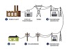
In case of Overhead transmission line system, the conductors
are run on the line supports, but if these conductors are not placed with
sufficient spacing causes the air between the conductors gets ionised and hence
a short circuit may occur in the transmission line. Therefore to avoid such condition we need Cross arms in the
transmission lines.

Cross-arm is
a cross-piece fitted to the pole top by means of brackets for supporting the
insulators.
Types of Cross-arms
The
following are different types of Cross-arms normally used in transmission lines
and are as shown in Fig. 3.5.
Features of Cross – arms :
1. The main function of Cross-arms is to keep the conductors at a Safe distance from each other as well as pole.
2. It provides safety to line staff while working on the pole.
3. It minimizes flash-over due to birdage.
4. It avoids conductors clashing due to windage.`
Economical spacing of conductors
The following
formula gives an economical spacing of conductors
D = 0.30480
[0.01 u + 1.315 d/g s]
Where, D – is the spacing in “meters”.
u – is the phase to phase
voltage in “kv”
G – is the
weight of the conductor in “kg/m”.
S – is the sag
in “meters”
D – is the
conductor diameter in “cm”
Nessesity for pole guys
In case of overhead transmission lines using poles will experiences will different pulls i.e. intermediate poles experience pull on either side which are equal and opposite for equal span lengths and the pull on the terminal pole is one side. Due to these pulls, the poles may tilt. Hence, it is very necessary to provide an additional arrangement to neutralize these pulls on the and such a arrangement is called Pole stay (or) pole guys.
Fig. 3.6
shows the Guy arrangement for the terminal poles.
In a straight run overhead transmission lines, the pull on
either side of the poles is equal and opposite so the intermediate poles are
safe from tilting. But during the abnormal weather conditions the poles and
conductors are subjected to high velocity winds in transverse direction to the
line due to which the poles may tilt. Hence, inorder to avoid this, every fifth
pole in a straight run is provided with guys, (or) stays on either side in
transverse direction as shown in Fig. 3.7
Methods of Fixing of Guys
There are
several types of fixing guy arrangement, namely
i. Fly
guy.
ii. Bow
Guy.
iii. Single and double guy
iv. Strut
Guy.
1. Fly Guy :
Sometimes it is not possible for arranging the stay structure on the existing
pole due to insufficient space. For this situation a special type of Guy
arrangement namely Fly guy is used and is as shown in Fig. 3.8.
The fly Guy arrangement will avoid
the anchoring of guy on the road.
2. Bow Guy : If
there is lack of sufficient space for the erection of the Guy, it becomes
necessary to keep the Guy spread to a minimum distance. For that one side of
Guy wire is fixed with a clamp on top of the pole and another end via a bracket
to another clamp near the bottom of the pole as shown in Fig. 3.9
3.
Single and Double Stay Arrangement :
4.
Strut Guy :


0 Comments