

Hydroelectric power plant explanation of each and every parts in detail

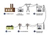
Shows the schematic arrangement of a hydro-electric power plant. The main requirement for hydro-electric power plant is the availability of water in huge quantity at sufficient head and it can be met by constructing a dam across a river or lake.
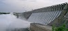
An artificial storage reservoir is formed by constructing a dam
across a river or lake and a pressure tunnel is taken off from the reservoir to
the valve house at the start of the penstocks. The value house contains main
sluice valves for controlling water flow to the power station and automatic
isolation valves for cutting off water supply in case the penstocks bursts. A
source tank is also provided just before the valve house for better regulation
of water pressure in the system.
The water from the reservoir is carried to valve house through
pressure tunnel and from valve house to the water turbine through pipes of
largest diameter made of steel or reinforced concrete called penstock. The
water turbine converts hydraulic energy into mechanical energy and
the alternator which is coupled on the same shaft of the water turbine will
converts mechanical energy into electrical energy. Water after doing useful
work is discharged to the tail race.
The following are the main requirements of be considered, for
construction of hydro-electric plants, namely.
1. Catchment area
2. Reservoir
3. Dam
4. Fore bay
5. Water ways
6. Draft tube
7. Surge tank
8. Spill way
9. Trash tracks
10. Power house and equipment.
1. Catchment area: The area behind the dam, which collects the rain water, drains in
to a stream (or) river is called “Catchment area “.
2. Reservoir: The place in which the water is stored in a dam is called
Reservoir. A reservoir may be natural (or) article. A natural reservoir is a
lake in high mountains and artificial reservoir is made by constructing a dam
across the river.
3. Dam : A dam is a structure of masonry (or) same other material built at
a suitable location across a river.
i) To
provides the following functions, namely
ii) To
create storage (or) pond age.
4. Fore bay: Water carried by the power canals is distributed to various
penstocks leading to the turbine, through the fore bays. Fore bays are mainly
used to store the water temporarily when the load is increased. Hence, the fore
bays will acts as a short of regulating reservoir.
5. Water way: A water way is used to carry the water from reservoir of the dam
to the power house.
6. Draft
Tube: Draft tube connects the runner exit to tail
race. Draft tube is a metallic pipe (or) concrete tunnel having gradually
increasing cross sectional are towards outlet to the tail race.
7. Surge
tank: A surge tank is a small reservoir (or)
tank in which the water level rises (or) falls to reduce the water hammerings
inside the conduit (penstock). The main function of surge tank is to provide
space for holding water during load rejection by the turbine and also supplies
an additional water when the load on the turbine increases. It also relieves
the water hammer pressures within the penstock under sudden changes in water
flow.
8. Spill ways: The spill ways provides discharge of
surplus water (or) flood water from storage reservoir in the downstream side of
the dam and it also serves as a safety value for the dam.
9. Trash tracks: These are mainly used to prevent the entry of debris to the
intakes from the dam.
10. Power house and equipment: power house consists of the main building
of hydro electric development and in which the conversion of water energy to
electric energy takes place.
Some important equipment provided in the power house are as
follows.
a) Turbine
b) Generators
c) Governors
d) Relief valves
for penstock fittings.
e) Gate valves
f) Flow
measurement equipment
g) Air ducts
h) Water
circulating pumps.
i) Transformers
j) Battery
room
k) Reactors.
l) Low
tension and high tension bus bars
m) Oil circuit breakers
n) cranes
o) Shop and offices


0 Comments